
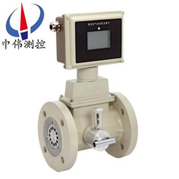
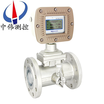
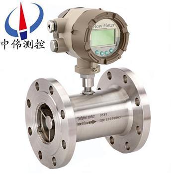

I. product overview
Zw-lw series turbine flowmeter is a kind of precision flow measuring instrument, which can display the total flow, instantaneous flow and flow full percentage. The intelligent meter head can display a large number of flow units, there are cubic meters, gallons, liters, standard cubic meters, standard liters, etc., can be set fixed pressure, temperature parameters for gas compensation, pressure and temperature parameters do not change the occasion, can be used for fixed compensation meter. Has the advantages of simple structure, light, high precision, good repeatability, responsive, use of installation and maintenance is convenient wait for a characteristic of a new generation of turbine flowmeter, it is widely used in measurement in a closed pipe with 1 cr18ni9ti stainless steel, 2 cr13 and corrode corundum Al2O3, cemented carbide, and no fiber, particles and other impurities, motion viscosity temperature less than 5 x 10⁻⁶ m2 / s of the liquid, the kinematic viscosity is greater than 5 x 10⁻⁶ m2 / s of the liquid, can be used for solid liquid flow meter calibration after. If it is matched with the display instrument with special functions, it can also be used for quantitative control, over-alarm, etc. It is an ideal instrument for flow measurement and energy saving.
Ii. Working principle
ZW - LW series turbine flow meter is a fluid flowing through the principle of the sensor shell, because of the impeller blade and flow to a certain point of view, the impact of fluid blade with rotational torque, to overcome the friction torque and fluid resistance, blade rotation speed stability after the moment balance, under certain conditions, the speed is proportional to the velocity of flow, because there are magnetic conductivity blade, it is in the signal detector (composed of * magnetic steel and coil) magnetic field, rotating blade cutting lines, periodically changing coil magnetic flux, so that the coil ends induction electrical pulse signal, the signal after amplifier amplification plastic, A continuous rectangular pulse wave with a certain amplitude can be formed, which can be transmitted to the display instrument to display the instantaneous flow of the fluid and the cumulative amount. Within a certain flow range, the pulse frequency f is proportional to the instantaneous flow rate Q of the fluid flowing through the sensor, and the flow equation is: Q=3600 f/k; Type:
F -- pulse frequency [Hz];
K -- instrument coefficient of the sensor [1/m3], given by the check list. If I take 1/L as the unit
Q -- instantaneous flow rate of fluid (under working condition) [m3/h];
3600 -- the conversion factor.
The instrument coefficient of each sensor is filled in by the manufacturer in the verification certificate, and the value of k is set in the supporting display instrument to show the instantaneous flow and cumulative total.
Iii. Application:
The flow sensor of zw-lw series turbine flowmeter and the display instrument form a turbine flowmeter. The sensor has the characteristics of high precision, good repeatability, long life and simple operation. Can be widely used in petroleum, chemical, metallurgy, papermaking and other industries to measure the volume of liquid instantaneous flow and volume total.
Iv. Main features:
1, small pressure loss, impeller with anti-corrosion function;
2, using advanced ultra-low power consumption single chip microcomputer technology, the machine features strong, low power consumption, superior performance;
3. Intelligent flow display with nonlinear precision compensation function. The accuracy of the modified formula is better than 0.02%.
4. The instrument coefficient can be set online by pressing the button, and can be displayed on the LCD screen, which is intuitive and clear with strong reliability;
5. EEPROM is used to protect cumulative flow and instrument coefficient from power failure, and the protection time is longer than 10 years;
6. Adopt high-performance MCU CPU to complete data acquisition, processing, display and output, and the cumulative flow is the same as the instantaneous flow;
7. Convenient man-machine interface for screen display, data transmission in standard 485 form;
8, the use of all hard alloy (tungsten carbide) shielding cantilever beam structure bearing, set of rotary bearing and pressure bearing in one, greatly improve the life of the bearing, and there is a small amount of sand and dirt in the medium work;
9. 1Cr18Ni9Ti stainless steel structure is adopted, (2Cr13 is adopted for turbine) with good anti-corrosion performance;
10, easy maintenance, self-rectifying structure, small and light, simple structure, can be assembled and disassembled in a short time, internal cleaning list;
11. Strong anti-magnetic interference and vibration ability, reliable performance, long life, low lower limit flow rate, wide measurement range;
12, field display LCD display clear and intuitive, low power consumption, 3V lithium battery power supply can run for more than 5 years, corrosion resistance, suitable for acid and alkali solution.
V. technical parameters:
1. Nominal diameter: pipe type: DN4 ~ DN200; Insert: DN100 ~ DN2000;
2. Accuracy grade: pipe type: 0.5, 1.0; Insert type: 1.5 level, 2.5 level;
3, environmental temperature: - 20 ℃ to 50 ℃;
4, medium temperature: liquid measurement: - 20 ℃ ~ 120 ℃; Measuring gas: - 20 ℃ ~ 80 ℃;
5. Atmospheric pressure: 86KPa ~ 106KPa;
6. Nominal pressure: 1.6 Mpa, 2.5Mpa, 6.4Mpa and 25Mpa;
7. Explosion proof grade: ExdIIBT4;
8. Connection: thread connection, flange clamping, flange connection, insert type, etc.;
9. Requirements for straight pipe segment: gas: upstream straight pipe segment should be 10DN, downstream straight pipe segment should be 5DN;
Liquid: upstream straight pipe segment should 20DN, downstream straight pipe segment should 5DN;
Insert type: the upstream straight pipe segment shall be 20DS, and the downstream straight pipe segment shall be 7DS(DS is the measured inner diameter of the pipe);
Display mode: (1) remote display: pulse output, current output (with display instrument);
(2) field display: 8-bit LCD display cumulative flow, unit (m3);
4 bit LCD display instantaneous flow, unit (m3/h), battery power, frequency and flow rate;
(3) temperature and pressure compensation type:
A. display standard instantaneous flow and standard cumulative flow;
B. Display current pressure, temperature and battery voltage;
11. Output function:
(1) pulse output, p-p value is determined by the power supply;
(2) 4-20ma two-wire current output;
(3) unit volume pulse output and sensor original pulse output;
(4) with RS485 communication interface;
12. Power supply:
(1) the DC5 ~ 24 v;
(2) standard 3V lithium battery can be installed in the instrument for more than eight years of continuous use;
(3) temperature and pressure compensation type 3V lithium battery can be installed in the instrument for more than four years of continuous use;
13. Transmission distance: the distance from the sensor to the display instrument is up to 500m.
Vi. Instrument type:
A. field display type:
The intelligent flowmeter is a new type of flowmeter display instrument designed by using advanced single chip microcomputer technology, which is matched with flow sensor (such as turbine and vortex) of pulse signal output. It can display instantaneous flow and accumulative total amount. Cumulative flow: eight digits, three significant digits after the decimal point. Instantaneous flow rate: six digits, showing variation per liter. Display precision: 1 display unit. Signal output: pulse output: 1~3000Hz external power supply +12~+24VDC power supply current output: 4~20mA external power supply +24VDC power supply (two-wire system) When the voltage is lower than 2.7v, the under-voltage indicator appears, flameproof type. Small signal removal function.
B. pulse output type:
Working voltage: +12VDC or +24VDC (customers must choose one power supply before ordering). Signal transmission distance: less than 250 meters. Installation: the amplifier and turbine flow sensor are connected with M16 1.5 threads. After installing the turbine flow sensor, screw the amplifier onto the turbine flow sensor. After feeling the amplifier to the bottom by hand, tighten the lock nut. Wiring: three external leads of pulse output amplifier, red line, white line and shield. The red line is connected to the positive power supply, the white line is connected to the pulse output and other display devices, and it is shielded and grounded
C. 4-20ma output type:
Working voltage: external power supply +24VDC (two-wire system) output signal: 4~20mA or 1-5v, 4mA corresponds to zero flow of turbine flow sensor. 20mA is used for turbine flow sensor zui with large flow. The flow range is shown in the nameplate of turbine flow sensor. Signal transmission distance: less than 250 meters. Installation: after installation of the turbine flow sensor, screw the amplifier to the turbine flow sensor junction (m16 1.5 thread), and tighten the lock nut when you feel the amplifier has reached the bottom by hand. Wiring: the external leads of 4~20mA output amplifier are red line and white line. The red line is the power line and the white line is the signal line.
D. split remote display type:
Working voltage: external power supply 220VAC signal transmission distance: less than 250 meters display instrument instantaneous four: cumulative total nine position display instrument size: horizontal: 160mm 80mm vertical: 80mm 160mm display instrument with 4~20mA output and can be connected to the computer.
Vii. Wiring and grounding precautions:
Wiring precautions
1. Use a complete cable as far as possible.
2. As far as possible, keep away from electrical noise sources (such as high-power transformers, motors and strong power lines) and avoid wiring parallel to power lines.
3. It is recommended to use non-soldered clamping lug at the end of thick wire.
4, in order to waterproof and mechanical damage, the cable into a metal tube, but the same tube shall not have a high-power transmission cable, (a transmission cable transmission zui high power is greater than the flow meter signal cable transmission zui low power 10 times, the two can not be installed in the same tube).
5. For the area with strong external magnetic field, the axis of the detecting device should be perpendicular to the magnetic flux direction of the external magnetic field or the flow sensor or external magnetic source should be shielded with high-permeability materials.
6. The connection of the cables of the explosion-proof turbine flow sensor must strictly comply with the relevant standards of the explosion-proof amplifier.
Grounding problem
1. The shielding wire can only be grounded at one end, and at the end of the display instrument.
2, reliable grounding should be good, explosion-proof type grounding resistance should be less than 10 Ω.
The following points must be noted when using turbine flow timing:
1. The tested medium is required to be clean, low viscosity, small corrosion, and free from impurities, so as to reduce the wear on the bearing. If the measured liquid contains gas or contains gas, install a deflator in front of the flowmeter. In order to avoid the impurities in the fluid into the transmitter to damage the weight, and in order to prevent the turbine stuck, it is necessary to add filters.
2. The installation of the flowmeter should avoid vibration, magnetic field and thermal radiation.
3. Changes in the density and viscosity of the medium have an impact on the flow indication value, which should be corrected if necessary.
Viii. Installation site:
1, the installation site should comply with the environmental temperature at 25 ~ 55 ℃ scope, humidity (80% RH
2, good ventilation, avoid the sun, rain
3. Avoid vibration or stress in piping
4. Avoid places susceptible to strong thermal radiation and radioactivity
5. Interference of external strong electromagnetic field on the detection signal must be avoided. If it can not be avoided, the flow meter (sensor) on the amplifier should be added to the shielding cover and other measures to eliminate interference.
6. Explosion proof amplifiers should be used in places with explosion proof requirements
7. The installation location should be considered to facilitate installation, operation and maintenance
Ix. Installation posture and position:
In order to ensure a high measurement accuracy, the flow meter (sensor) should be installed horizontally in a horizontal pipe, and the flow direction of the arrow indicating the flow direction of the flow sensor should be consistent with the flow direction of the liquid. If vertical installation is necessary, the flow of liquid should be from bottom to top to ensure that the flow sensor body is filled with liquid.
X. piping requirements:
1. In order to eliminate the influence of uneven distribution of cross-section velocity in the pipeline on the measurement accuracy, the upstream and downstream of the flow sensor should have a certain straight section, or rectifier should be installed to replace part of the straight section. Generally, the upstream straight pipe segment shall not be less than 15D, and the downstream straight pipe segment shall not be less than 5D (D is the nominal diameter of the flow sensor).
2. In order to eliminate the influence of backflow, uneven distribution of flow velocity and swirling flow, a rectifier can be installed on the upstream. At this time, the length of the straight pipe in the upstream part of the flow sensor L=10D is ok.
3, when the measured liquid contains solid impurities, should be installed in the upstream of the flow sensor filter, filter mesh number of 20 ~ 60 mesh (3 ~ 9 mesh /cm2), the general flow sensor aperture small mesh number more. The installation location of the filter should be considered to facilitate the removal and installation of the filter.
4. When the liquid is mixed with gas or easily vaporized liquid is measured, an air separator (air eliminator) shall be installed.
5. If the measured liquid is easily gasified, in order to prevent cavitation, the pressure at the outlet of the flow sensor should be higher than the Pmin calculated in the following formula:
Pmin = 2 P 1.25Pv: Pmin -- zui low pressure; Pressure loss of the flow meter;
Pv -- zui saturation vapor pressure of the liquid under test at high service temperature
6, the flow through the flow sensor is too large, will make the bearing life is too short, usually through the valve will flow to the appropriate size, the valve should be installed in the downstream of the flow meter.
7. In order not to interrupt fluid transportation during maintenance, globe valves are usually installed in the upstream and downstream of the flow sensor, and bypass pipes are set at the same time, and the bypass pipes shall not leak when the bypass valve is closed during measurement.
8. If reverse flow is possible, check valve should be added to prevent reverse flow of fluid.
9. The flow sensor shall be concentric with the pipe, and the sealing ring shall not protrude into the pipe.
10. To avoid gas accumulation in the flowmeter, the flowmeter should not be installed on the zui high point of the horizontal pipeline.
11. If the flow meter is installed at the low point of the pipeline, the discharge valve should be installed in the pipeline to discharge sediment regularly.
12. The front and rear pipelines of the flow sensor shall be firmly supported without obvious vibration.
13. When cleaning the newly laid pipeline, a short pipe shall be connected to the position where the flow sensor is installed, and the flow sensor shall be installed after the cleaning is completed.
14. When the temperature of the fluid needs to be measured, it shall be measured at the length of 5 times the nominal pipe diameter downstream of the flow sensor.
15. When the pressure of the fluid needs to be measured, it shall be measured at the length of 10 times the nominal pipe diameter upstream of the flow sensor.
11. Possible problems caused by installation:
1. Insufficient length of upstream and downstream straight pipe segments;
2. There is a big deviation between the inside diameter of the instrument measuring pipe and that of the pipe fitting;
3, installation of different heart, sealing pad convex tube;
4. Reverse instrument flow direction;
5. Detection elements are covered with impurities;
6. Low detection sensitivity and low flow rate;
7, pipeline leakage (such as installed in the underground pipeline, small leakage is not found), valve leakage, bypass valve leakage caused by the cumulative flow (total) is small;
8. Accurately measure the influence of two-phase flow and pulsating flow.
Xii. Matters needing attention in storage:
The flowmeter should be installed in time after it arrives. For the battery powered lrt-i meter head, the power pin should be placed in the "OFF" (disconnected) position when not in use, so as to avoid the impact of battery power consumption on the service life of the battery. For storage, please note the following:
1. Do not open the packing box for storage under possible conditions.
2. If the package has been opened or the meter has been used, please plug the lrt-i meter head power jumper in the "OFF" position and use the original package.
The storage place shall meet the following conditions:
